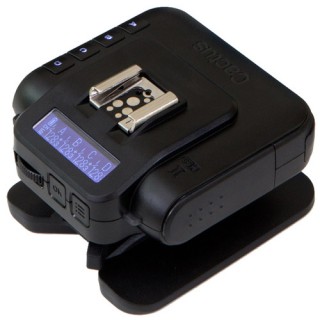
With my recently broken flash transceivers (read about that here) being just a few months out of its 1-year warrantee I decided to open it up and attempt to fix it myself. During the process I found some interesting things I though I’d share.
I have two other Cactus V6 transceivers that work great. The V6II has always had some issues since it was brand new. The foot easily rotates or wiggles in the hot shoe, the firmware was buggy, it did not support TTL and HSS on Fuji for the longest time even though they claimed it worked. Thankfully a few software updates from both Cactus and Fuji fixed the HSS and TTL issues. The hot shoe issue was still a huge problem. Randomly the pins would misalign and the V6II would not fire at all so I kept around and extra V6 incase it stopped working all together.
When the switch on my V6II broke I decided to see if I could also fix the hot shoe wiggling issue. It was fairly simple to take apart the unit. 4 screws hold it together with a few ribbon cables connecting everything. If you have ever replaced an iPhone screen or similar you will find this fairly easy. The bottom half of the unit contains the hot shoe connector. This is secured with three screws. I found that by tightening these screws the shoe stopped wiggling. The downside of course is that over tightening of the screws causes them to protrude from the hotshoe foot and it will not insert into the camera.
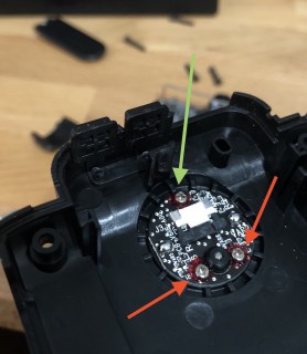
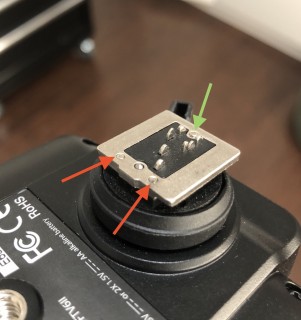
I tightened the two screws in the front of the unit until they were flush with the foot (red), about 1/4 turn. I then tightened the rear screw (green) until snug since it never fully enters the hotshoe on my Fuji. This has removed all play and wiggle from the V6II. It looks like Cactus simply used screws that were slightly too long and could not tighten them enough without them protruding.
Next up was the on/off switch. It has 3 positions, Tx, off, Rx. I located all the parts that were rattling around inside and was surprised to see how Cactus had constructed it.
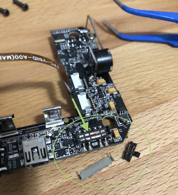
Yes, that’s right, it’s not a sealed, self-contained switch but rather a plastic box with a sliding plastic/metal contact and a metal cover plate holding the whole thing together!
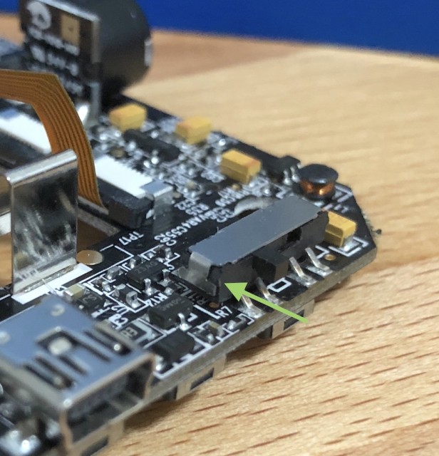
It was fairly strait forward to put together. you can see how the metal tabs lock into the plastic sides. It is also clear that the slightest bit of upward force put onto the switch could release the metal cover plate, as it did for me, rendering the entire unit broken. I did my best to bend the metal tabs so they would hold more securely but it seems likely it could pop off again.
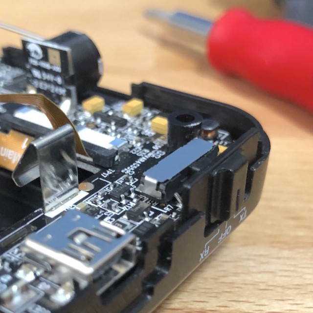
Hopefully this will help someone else with a broken power switch on their Cactus V6II transceiver. While I love the functionality of the Cactus system I don’t know if I can count on it to work when I need it. I may be switching soon to the Flashpoint/Godox 2.4ghz line of flashes now that they are Fuji compatible.


